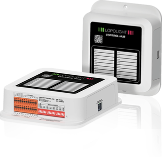
Lopolight®
Control Hub
Monitoring and control off navigation
lights and other equipment trough
your Chart plotter (MFD)
CONTROL YOUR:
• Nav lights
• Boom lights
• Cockpit lights
• Spreader lights
• Docking lights
• Wipers
• Fans
• Pumps
• Bilge sensor
and more ...


LOPOLIGHT CONTROL HUB
INTRODUCING A NEW WAY TO MONITOR AND CONTROL YOUR LIGHTS – AND OTHER EQUIPMENT ON SMALLER VESSELS.
The Lopolight Control Hub connects to chartplotters (MFD) from leading manufacturers – giving intuitive operation, compact installation, and easy configuration.

APPROVED
MFD BRANDS


Location of install the Control Hub
Manual override for emergency usage
The cabinet needs to be located accessible, to be able to control the manual override switches.
Water ingress
The location needs to be in a dry area to avoid water ingress.
Ventilated location
The chosen location needs to be in a well-ventilated area, to avoid unnecessary overheating.
Power supply
Power input to the unit shall be 12-24VDC (10-32VDC), and the positive supply wire shall be of “a reasonable dimension”, scaled to carry the theoretical maximum load of all connected equipment. The size of the main fuse shall also be considered.
Guideline: 1.5-2 mm2. Maximum length from DC distributor rail: ~1 meter / 3 feet.
Ethernet connection
Use CAT5 or higher quality rated ethernet cable. Or use original Raymarine Raynet or Garmin Marine Network ethernet cables.
EMC Guidelines
In areas of extreme EMC interference, interference may be noticed on the product. Where this occurs the product or the source of the interference should be relocated.
Compass interference
In case you experience compass interference, the Control Hub needs to be relocated at least 1 meter (3 feet) away from the compass.
Compatible MFD’s (Multifunction Displays)
Connect Ethernet to MFD
The Control Hub is delivered without Ethernet cable, the Control Hub has an RJ45 Ethernet connection. For Raymarine MFD’s a Raynet to RJ45 cable is required. For Garmin MFD’s a Marine Network Cable or Connector Kit required (see information below).

OUTPUT AND "CONSUMER"
There are 16 outputs, these can be used for all types of power consumers such as lanterns, deck lights, boom lights and more. The individual ’consumer’ must not exceed 2A and the whole unit has a maximum load of 10A. The unit operates at 10-32 VDC.
OUTPUT CONNECTIONS
The output terminals are presented in a direct cable terminal block at the bottom of the box. Power enters through the same terminal connection which also contains the outputs. Including alarm output etc.
ALARM INDICATIONS
The monitoring is performed as a current monitoring, and an alarm is given in the event of a lack of power consumption. The unit has an output for an audible alarm, which can be placed freely and controlled via the MFD interface.
Termination of connection wires
The use of strand-protection ferrules
is recommended when terminating
wires in the Control Hub.
The basic recommended standard wire gauge is 1 mm2 (17AWG) for max. 2A output, but can and shall be optimized to suit the individual 11 application according to accepted voltage drop, power consumption, good craftmanship and local rules.
PWM dimming control (200Hz)
Channel number 1 and 14 can be set-up for PWM dimming purposes. If not used for PWM they can be used as any of the remaining outputs.
Avoid using channel 1 and 14 for inductive loads (relay coil or electric motor). The PWM function is activated in the individual channel setting.
When selected a control bar will appear on the main page. The dimming output on channels 1 and 14 can deliver up to 2A.
NOTE: When used to control Lopolight Decklights (400-22x series) these outputs can control up to ~30 dedicated PWM inputs.
Grouped lights/channels external hardware control
The Control Hub has 4 hardware button
inputs for controlling a group of channels.
